
Since I know the digital gyroscope I have a particular interest by this component, due the fact of being used in a lot of modern systems, like smartphones or aircraft industries.
To participate on Lisbon Maker Faire I built a project that used this amazing component, called Self Balancing Robot [SBR].
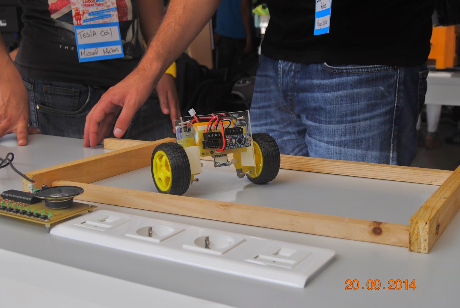
The SBR helps to understand the principles behind the Segway vehicles. The robot stands in two wheels using the gyroscope inclination readings to position the mass center of the robot in vertical.
Bill of Materials
1-Arduino Nano V3.0 ATmega328P 5V Board
2-MPU-6050 3 Axis Accelerometer Gyroscope Module
3-DC Gear Motor With Wheel
4-Battery Rhino 610mAh 2S 7.4v 20C Lipoly Pack
5-Battery Charger HobbyKing™ E4 Balance Charger
6-Motor Driver L293D - Quadruple Half-H Driver
7-PCB 33x70 mm Single Side Copper + Silkscreen by: eLab
8-Acrylic 100x90x4,74
9-Screws/Bolts/Metals
L293D - QUADRUPLE HALF-H DRIVERS
The L293D is designed to provide bidirectional drive current of up to 600mA (1.2A peak) at voltages from 4.5V to 36V. Its designed to drive inductive loads such as relays, solenoids, dc and bipolar stepping motors, as well as other high-current/high-voltage loads in positive-supply applications.
All inputs are TTL compatible. Each output is a complete totem-pole drive circuit, with a Darlington
transistor sink and a pseudo-Darlington source.
Drivers are enabled in pairs, with drivers 1 and 2 enabled by 1,2EN and drivers 3 and 4 enabled by 3,4EN. When an enable input is high, the associated drivers are enabled, and their outputs are active and in phase with their inputs. When the enable input is low, those drivers are disabled, and their outputs are off and in the high-impedance state. The next image shows the block diagram.

Purchased on HobbyKing.com, this 7.4V battery can provide 610mAh (capacity) and contains two cells of 3.7V each connected in series (2S). The discharge rate (20C) means this battery can discharge safely 20 times more than the capacity of the pack.
So far the autonomy was between 3 to 4 hours and the charge took 30 to 50 minutes.


Gyroscope + Accelerometer MPU6050
The MPU-6050 is an integrated 6-axis MotionTracking device that combines a 3-axis gyroscope, 3-axis accelerometer, and a Digital Motion Processor™ (DMP). It features three 16-bit analog-to-digital converters (ADCs) for digitizing the gyroscope outputs and three 16-bit ADCs for digitizing the accelerometer outputs.
The triple-axis MEMS gyroscope in the MPU-6050 includes Digital-output X, Y, and Z Axis angular rate sensors (gyroscopes) with a user-programmable full-scale range of ±250, ±500, ±1000, and ±2000°/sec and the triple-axis MEMS accelerometer includes Digital-output triple-axis accelerometer with a programmable full scale range of ±2g, ±4g, ±8g and ±16g.
Communication with all registers of the device is performed using I2C at 400kHz. I2C is a two-wire interface comprised by the signals serial data (SDA) and serial clock (SCL). In general, the lines are open-drain and bi-directional. In a generalized I2C interface implementation, attached devices can be a master or a slave, the master device puts the slave address on the bus, and the slave device with the matching address acknowledges the master. The MPU-6050 always operates as a slave device when communicating to the system processor, which thus acts as the master.
The slave address of the MPU-6050 is b110100X which is 7 bits long. The LSB bit of the 7 bit address is determined by the logic level on pin AD0. This allows two MPU-6050s to be connected to the same I2C bus.
Additional features include an embedded temperature sensor and an on-chip oscillator with ±1% variation over the operating temperature range.

The MPU-6050 is built using three independent vibratory gyroscope MEMS , which detect rotation in the X, Y, and Z Axis. When the gyros are rotated about any of the sense axis, the Coriolis Effect causes a vibration that is detected by a capacitive pickoff. The resulting signal is amplified, demodulated, and filtered to produce a voltage that is proportional to the angular rate. This voltage is digitized using individual on-chip 16-bit Analog-to-Digital Converter (ADCs) to sample each axis.

The accelerometer uses separate proof masses for each axis. Acceleration along a particular axis induces displacement on the corresponding proof mass, and capacitive sensors detect the displacement differentially. The MPU-6050 architecture reduces the accelerometer susceptibility to fabrication variations as well as to thermal drift. When the device is placed on a flat surface, it will measure 0g on the X and Y axis and +1g on the Z-axis. The accelerometer scale factor is calibrated at the factory and is nominally independent of supply voltage. Each sensor has a dedicated sigma-delta ADC for providing digital outputs. The full scale range of the digital output can be adjusted to ±2g, ±4g, ±8g, or ±16g.

Printed Circuit Board and Schematics
The printed circuit board was made in KiCad version 2013-07-07 BZR 4022 Stable. Some components were custom made and some from specific libraries including the 3D models. The next image shows the schematic.

On the next images is shown the Printed Circuit Board and its 3D model ready to print and start the fabrication.


The next image shows some steps to fabricate the PCB. In general steps it was used the toner method and etching with muriatic acid and hydrogen peroxide.

The next image shows the components in place and the PCB mounted on the acrylic.

Algorithm
The Arduino Nano receives the gyroscope readings by I2C. Due the noise introduced into the circuit by motors, the readings floated a lot. To compensate this fact it was used a Kalman filter, to filter those nasty peak readings keeping values in a steady level.
The gyro offset was adjusted to 0 degrees on robot mass center. The gyro took readings on y axis tilt. Between 18 to -15 degrees it was defined the main operation area for the robot and in this area the microcontroller will send 5ms pulses to the wheels, and if the structure was perfectly aligned in 0 degrees the wheels totally stopped.
The second defined operation area was defined to 50 degrees, with 10ms pulses to the wheels. These stronger pulses permitted to align the mass center faster, to don’t let the block misalign to a danger area, never recover and fall to the floor.
The third defined region was a safety feature. When the robot is horizontally aligned the wheels are disconnected to guarantee that the robot do not run away. The code is available in my Github.
Final
The SBR was ready to the Lisbon Maker Faire. The feedback of the visitors was positive and I also received improvement suggestions like Bluetooth control with a mobile app. It was a fantastic opportunity to build something and see people's reaction in first place!
The next photos and videos show the final results :)


Special thanks to the eLab team for the motivation and final adjustments :)